
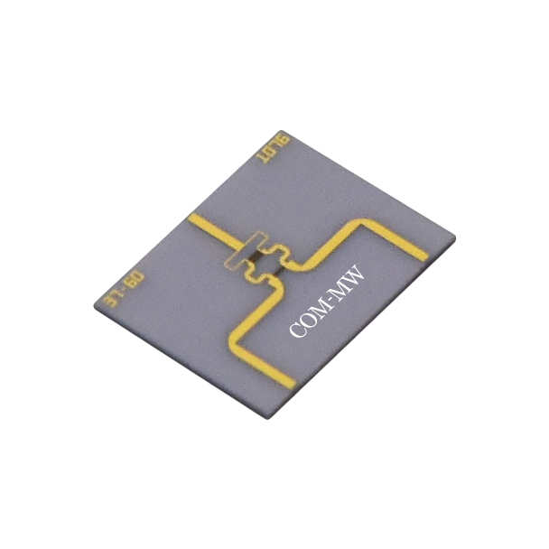
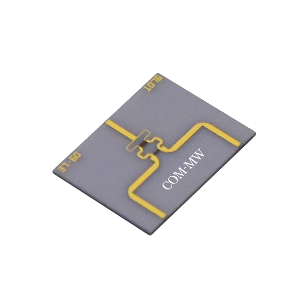
30~36GHz, 1W, 2way, Phase0°
To check stock availability, search under "In-stock Products" on the Dianzibuy store.
Any change to the content of this page is subject to change without notice. Please confirm the specifications before ordering.
Products must not be used for any unlawful purpose; the customer bears any loss arising from unlawful use.
| Parameters | Min | Typical | Max | Units |
|---|---|---|---|---|
| Frequency | 30 | ~ | 36 | GHz |
| Center loss | 0.5 | dB | ||
| Isolation | 20 | dB | ||
| Input VSWR | 1.5 | |||
| Output VSWR | 1.5 | |||
| Amplitude balance | 0.3 | dB | ||
| Phase balance | ±6 | ° |
| Power Capacity | 1W Design assurance |
| X-Way | 2-way |
| Phase | 0° |
| Impedance | 50Ω |
| Connector | Microstrip pad |
| Operation Temp. | -40~+85℃ Design assurance |
| Other | Thin film ceramics |
| Common port | 0 |
| Dispatch Port | 1,2 |
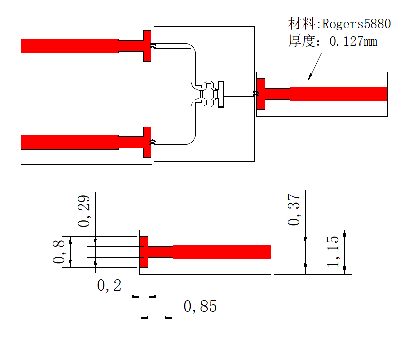
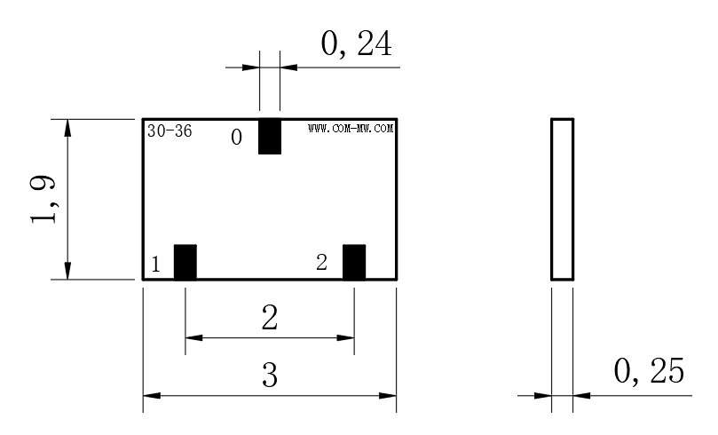
| 1 | The chip is recommended to be used in separate cavities, with a distance of 0.1mm from the sidewall on one side and a distance of 1-2mm from the upper cover on the surface. |
| 2 | Low stress conductive adhesive (ME8456) is recommended for bonding chips. |
| 3 | The chip should be installed on a carrier such as molybdenum copper, which is close to the thermal expansion coefficient of ceramics (6.7ppm/C °), with a carrier thickness of ≥ 0.2mm. |
| 4 | When the Microstrip of the circuit board is bonded to the chip, it is recommended to use a T-shaped structure at the microstrip bonding point for matching. |
Send us your requirements — our engineers will respond within one working day.