
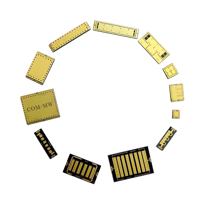
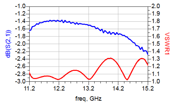
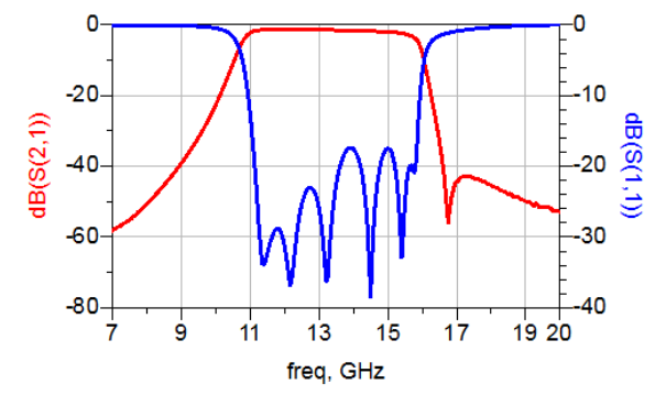
Passband11200~15200MHz, 9.9&16.45GHz≥20dB, 9.35&16.65GHz≥30dB, Microstrip pad, MEMS
To check stock availability, search under "In-stock Products" on the Dianzibuy store.
Any change to the content of this page is subject to change without notice. Please confirm the specifications before ordering.
Products must not be used for any unlawful purpose; the customer bears any loss arising from unlawful use.
High precision silicon-based MEMS processing technology,
50 Ω coplanar waveguide output, gold wire bonding.
| Parameters | Frequency | / | Min | Typical | Max | Units |
|---|---|---|---|---|---|---|
| Passband | / | / | 11200 | ~ | 15200 | MHz |
| Center loss | / | / | 1.8 | dB | ||
| Ripple | / | / | 1.2 | dB | ||
| Rejection | 9.9&16.45 | GHz≥ | 20 | dB | ||
| Rejection | 9.35&16.65 | GHz≥ | 30 | dB | ||
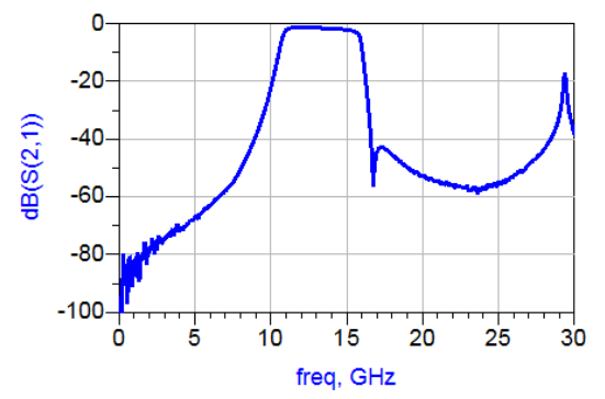
| Rejection | DC-8.65 | GHz≥ | 40 | dB | ||
| Rejection | 16.8-27.4 | GHz≥ | 40 | dB | ||
| Passband VSWR | / | / | 1.6 |
| Connector | Microstrip pad |
| Impedance | 50Ω |
| Power Capacity | 35dBm Design assurance |
| Delay ripple | ≤0.5ns |
| Phase balance | ≤±5° |
| Operation Temp. | -55~+85℃ Design assurance |
| Storage Temp. | -55~+125℃ Design assurance |
| Quality Grade | Industrial grade |
| ROHS | Compliant Available |
| Filter Category | MEMS |
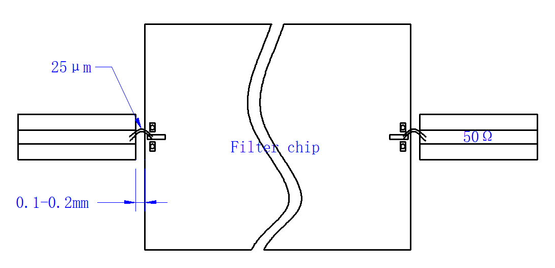
1. The chip is recommended to be installed in a metal cavity, with a distance of 0.1mm from the side walls on both sides of the chip, and a gap of ≥ 3mm between the upper surface of the chip and the metal shielding cover plate,
2. It is recommended to use low-temperature solder or low stress conductive adhesive for chip soldering,
3. The chip should be installed on a carrier with a thermal expansion coefficient equivalent to that of silicon (2.9ppm/℃), such as Kovar, with a carrier thickness of ≥ 0.2mm,
4. When bonding microstrip lines to chips, it is recommended to use a 50 μ m × 10 μ m gold strip or two 25 μ m gold wires, with the gold wire (gold strip) as short as possible,
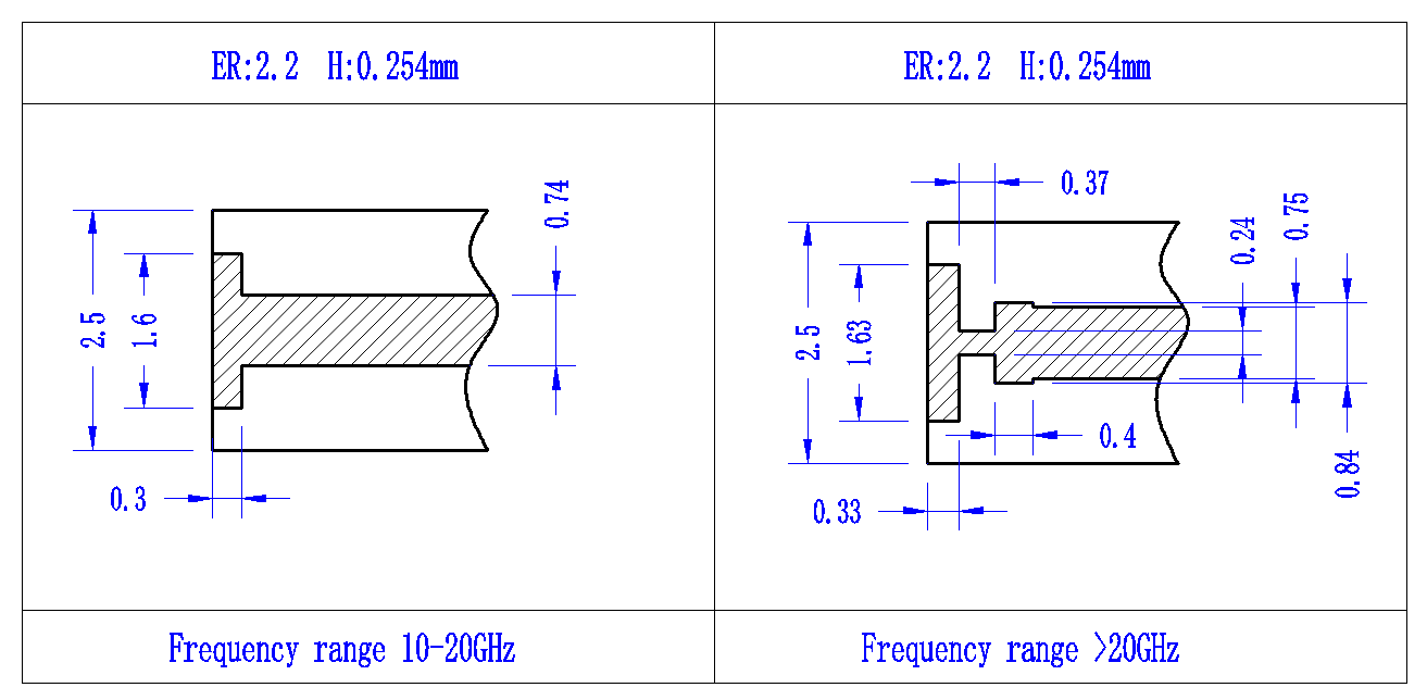
5. When the passband frequency of silicon-based MEMS microstrip bandpass filters is above 10GHz, it is recommended to use a T-shaped structure for matching at the microstrip line bonding.
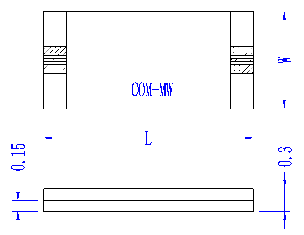
| Size Code | Mini value (mm) | Nominal value (mm) | Max value (mm) |
|---|---|---|---|
| L | 2.4 | 2.5 | 2.6 |
| W | 2.7 | 2.8 | 2.9 |
Send us your requirements — our engineers will respond within one working day.