
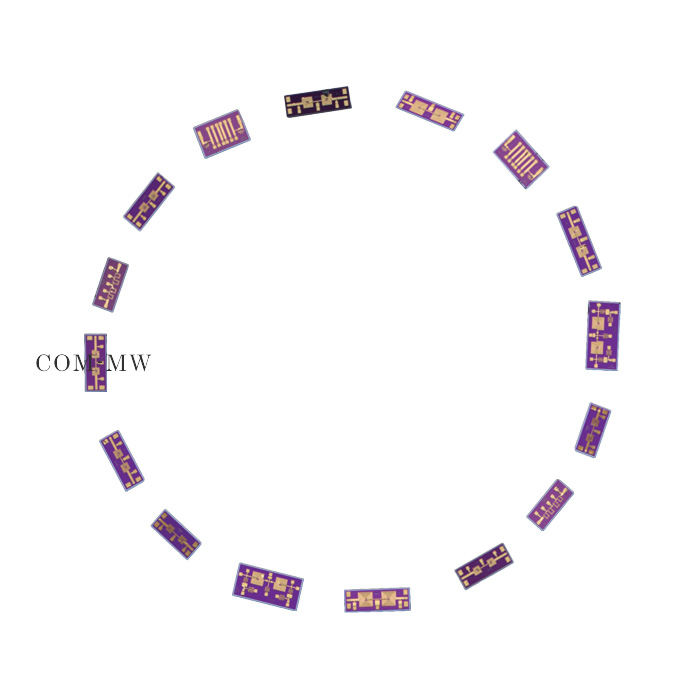
Passband1250~1450MHz, 800MHz≥30dBc, 2000MHz≥30dBc, Microstrip pad, MMIC
To check stock availability, search under "In-stock Products" on the Dianzibuy store.
Any change to the content of this page is subject to change without notice. Please confirm the specifications before ordering.
Products must not be used for any unlawful purpose; the customer bears any loss arising from unlawful use.
Mature GaAs processing technology,
50 Ω coplanar waveguide output, gold wire bonding.
| Parameters | Frequency | / | Min | Typical | Max | Units |
|---|---|---|---|---|---|---|
| Passband | / | / | 1250 | ~ | 1450 | MHz |
| Center loss | / | / | 1.9 | dB | ||
| Ripple | / | / | 1.0 | dB | ||
| Rejection | 800 | MHz≥ | 30 | dBc | ||
| Rejection | 2000 | MHz≥ | 30 | dBc | ||
| Passband VSWR | / | / | 1.5 |
| Connector | Microstrip pad |
| Impedance | 50Ω |
| Power Capacity | 25dBm Design assurance |
| Operation Temp. | -55~+125℃ Design assurance |
| Storage Temp. | -65~+150℃ Design assurance |
| Quality Grade | Industrial grade |
| ROHS | Compliant Available |
| Filter Category | MMIC |
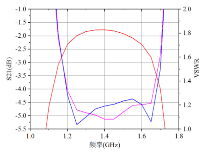
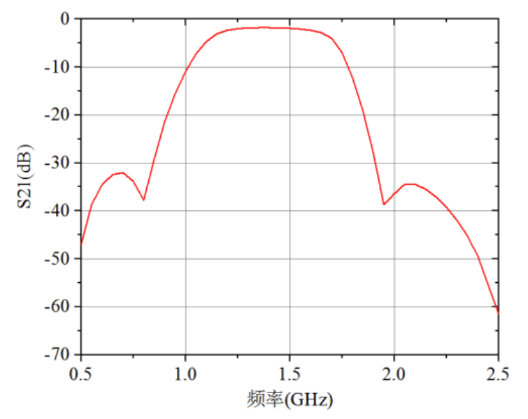
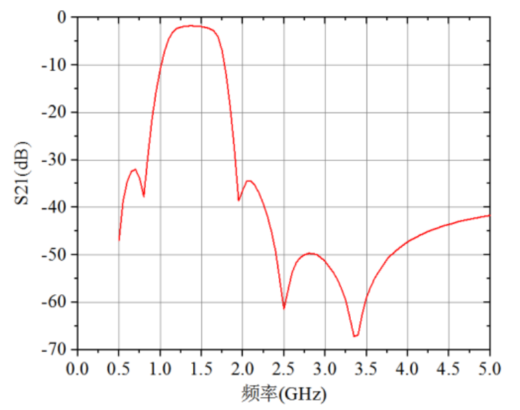
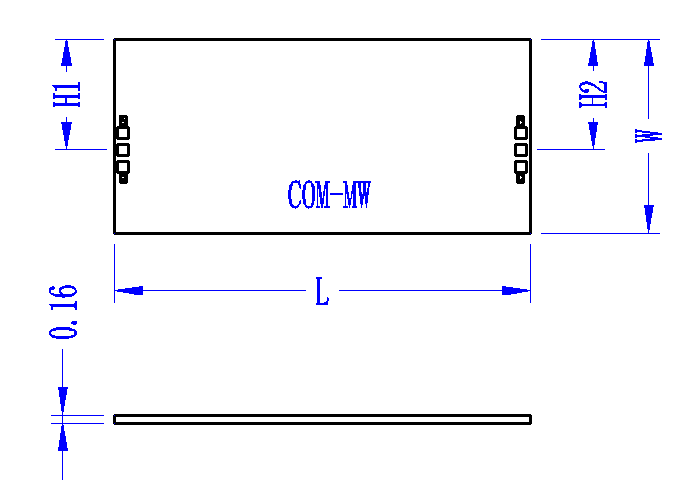
| Size Code | Mini value (mm) | Nominal value (mm) | Max value (mm) |
|---|---|---|---|
| L | 2.65 | 2.7 | 2.75 |
| W | 1.55 | 1.6 | 1.65 |
| H1 | 0.77 | ||
| H2 | 0.77 |
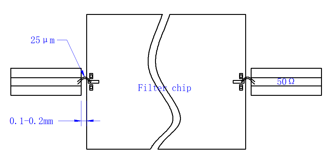
1. Storage: The chip must be placed in a container with electrostatic protection function and stored in a nitrogen environment.
2. Electrostatic protection: Please strictly comply with ESD protection requirements to avoid electrostatic damage to devices.
3. Conventional operation: Avoid tool or finger contact with the chip surface during operation.
4. Mounting operation: Chip installation can be carried out using AuSn solder eutectic sintering process or conductive adhesive bonding process, and the mounting surface must be clean and flat.
5. Sintering process: Use AuSn solder with a gold tin ratio of 80/20. The temperature should not exceed 295 degrees, and the friction time should not exceed 3 seconds.
6. Bonding process: The amount of conductive adhesive should be minimized as much as possible. After placing the chip in the installation position, the conductive adhesive can be seen around it.
7. Bonding operation: Ball or wedge bonding uses 0.025mm gold wire and is carried out according to the general process.
Send us your requirements — our engineers will respond within one working day.